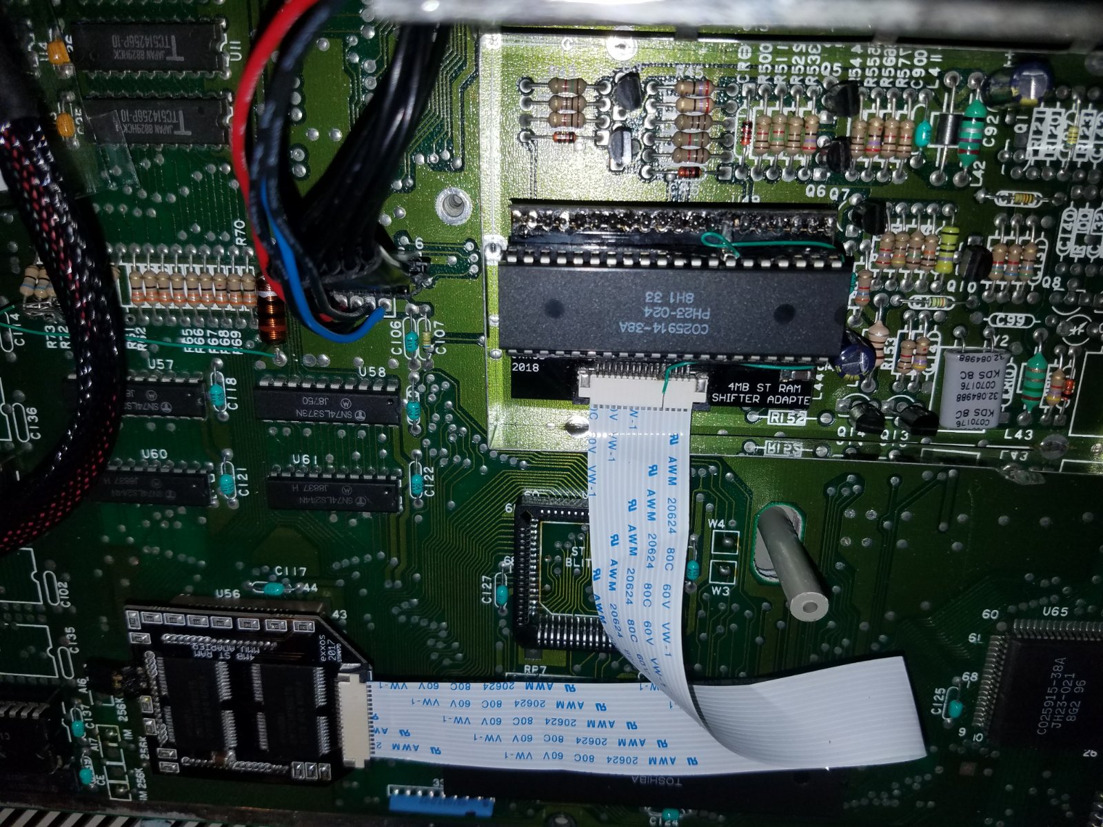
Few months ago I purchased the 4MB MMU TYPE RAM UPGRADE from Exxos site, and I never was able to get it running.
I first tried to install it into 520STM (pictured) C070243 Rev. H. I consider myself pretty good with soldering iron and putting the shifter adapted together was easy. I desoldered one end of R133 and R134 and connected it to 5V.
Before powering on the machine, I double-cheked with voltmeter in continuity mode that I don't have any shorts and everything checked ok. So, I powered on the machine and all I saw was bunch of color bars.
Since my TOS was v1.0, someone suggested here on the forum for one of the posts to upgrade the TOS to v1.4. I did that and color bars turned into black screen with white bars and it still didn't work.
Next I added pins for the 1mb/4mb jumper and tried in the 1mb mode, but that didn't help
There was another post here where it was suggested to remove the ram chips. (https://www.exxosforum.co.uk/forum/viewt ... =29&t=1549) I tried that as well and still got same results. Btw, if I removed the Ram Upgrade boards, the machine ran as ussual.
Since my C070243 Rev. H board looked a little different than Spiny's C070243 Rev. H used in http://www.spiny.org/atari/photos/exxos_4meg_stm/ (Notice how on my board the following were populated C107,C127,C108,C121, and unmarked capacitor next to U45) and the user from the link above had the same issue as me, I thought that it might be that this revision was not supported. So, I got another spare 520STM with C070243 Rev. B and Ram Upgrade produced the same results. At this point, I thought that maybe this upgrade does not work with NTSC machines, I also aquired an 1040STF C103175 Rev.1. It had a soldered MMU which I removed with the heatgun and added the socket and small adapter for the RAM MMU adapter board, and still got the same result.
I like finding faults and fixing things myself, but at this point I am out of ideas without schematic. I'm convinced that the either board(s) or ram chips are faulty. I find it very unlikely that I maybe didn't solder something right since it was just the socket and the pins. Everything else came pre-assembled. By now I checked numerous times for shorts on all the pins on all points (socket, cable header, ram chips, pins on the shifter adapter and on the MMU adapter) and everything seems ok.
Is there anything else I can do to check the boards or the chips?
Help - Issue with Exxos 4MB RAM UPGRADE
-
HeavyMetal
- Posts: 3
- Joined: 19 Mar 2020 06:56
Help - Issue with Exxos 4MB RAM UPGRADE
You do not have the required permissions to view the files attached to this post.
-
exxos
- Site Admin

- Posts: 28388
- Joined: 16 Aug 2017 23:19
- Location: UK
Re: Help - Issue with Exxos 4MB RAM UPGRADE
I would meter out the ribbon connectors solder points on the MMU board to the shifter pins. Looks like there is a bad signal on that ribbon cable somewhere.
Just put your meter probe on beep test on the first pin on the MMU connector and run the other probe down the pins on the shifter.. It should beep on one of the shifter pins for each of the 16 wires.
You do not have the required permissions to view the files attached to this post.
-
rubber_jonnie
- Site Admin

- Posts: 14917
- Joined: 17 Aug 2017 19:40
- Location: Essex
Re: Help - Issue with Exxos 4MB RAM UPGRADE
One thing I'd look at after following the advice from @exxos is to check the MMU adapter orientation. At least one ST mainboard I know of has the MMU 180 degrees rotated from where you'd expect it to be.
Make sure the pin 1 of the MMU adapter and the MMU socket are correctly aligned, as I fell foul of this once myself.
Also be 100% sure that the MMU adapter is correctly pushed all the way home or you may have contact issues. It will need to be pushed quite far in going by my experiences of other types, such as Marpet and Frontier adapters.
Double check you havent accidentally bent one of the pins too. I've done this and it isn't easy to see unless you pull the adapter out again.
Make sure the pin 1 of the MMU adapter and the MMU socket are correctly aligned, as I fell foul of this once myself.
Also be 100% sure that the MMU adapter is correctly pushed all the way home or you may have contact issues. It will need to be pushed quite far in going by my experiences of other types, such as Marpet and Frontier adapters.
Double check you havent accidentally bent one of the pins too. I've done this and it isn't easy to see unless you pull the adapter out again.
Collector of many retro things!
800XL and 65XE both with Ultimate1MB,VBXL/XE & PokeyMax, SIDE3, SDrive Max, 2x 10¹⁰ cassette, 2x 1050 one with Happy mod, 3x 2600 Jr, 7800 and Lynx II
Approx 20 STs, including a 520 STM, 520 STFMs, 3x Mega ST, MSTE & 2x 32 Mhz boosted STEs
Plus the rest, totalling around 50 machines including a QL, 3x BBC Model B, Electron, Spectrums, ZX81 etc...
800XL and 65XE both with Ultimate1MB,VBXL/XE & PokeyMax, SIDE3, SDrive Max, 2x 10¹⁰ cassette, 2x 1050 one with Happy mod, 3x 2600 Jr, 7800 and Lynx II
Approx 20 STs, including a 520 STM, 520 STFMs, 3x Mega ST, MSTE & 2x 32 Mhz boosted STEs
Plus the rest, totalling around 50 machines including a QL, 3x BBC Model B, Electron, Spectrums, ZX81 etc...
-
HeavyMetal
- Posts: 3
- Joined: 19 Mar 2020 06:56
Re: Help - Issue with Exxos 4MB RAM UPGRADE
Exxos and RJ, thank you very much for the response and suggestions. I did all of your suggestions in the past and did it one more time, just for the sake of it and I'm still getting the same response. There is one thing that I noticed, that I remembered after I posted the last post which I forgot to mention that I wasn't sure if it was correct since I did not have schematics and I couldn't verify. I have 2018 version of Exxos' shifter board and when I measured continuity, I got continuity between the ground leg of the capacitor and pins 20 and pins7 on the socket (see attached picture). Pin 20, if I'm not mistaken is ground so that would make sense, but D4 on pin 7 seems odd. Can you guys confirm if pin 7 should be connected to the ground?
Thanx
Thanx
You do not have the required permissions to view the files attached to this post.
-
exxos
- Site Admin

- Posts: 28388
- Joined: 16 Aug 2017 23:19
- Location: UK
Re: Help - Issue with Exxos 4MB RAM UPGRADE
With the shifter board in place with original ram I assume the machine doesn't boot ?
GND on D4 isn't correct no...must be a short on the board somewhere..
-
exxos
- Site Admin

- Posts: 28388
- Joined: 16 Aug 2017 23:19
- Location: UK
Re: Help - Issue with Exxos 4MB RAM UPGRADE
Could only assume D4 is shorting to the GND fill somewhere.
You do not have the required permissions to view the files attached to this post.
-
rubber_jonnie
- Site Admin

- Posts: 14917
- Joined: 17 Aug 2017 19:40
- Location: Essex
Re: Help - Issue with Exxos 4MB RAM UPGRADE
I'd agree with @exxos in that D4 should not be linked to GND.
Also, I'm aware that the shifter adapter does come as a kit, so I've zoomed in and had a look at the solder joints for the headers and socket and some look like they might be dry/cold, so I'd be tempted to suggest you may want to reflow to be sure these are gone, and to clean up any excess solder.
Zooming in I don't see any obvious solder bridges around the board.
Since it fails on other machines, I think it likely that the shifter adapter is the culprit, but even so I'd double check the socket you installed.
Also, did you check D4 with the adapter plugged in or on the workbench?
Also, I'm aware that the shifter adapter does come as a kit, so I've zoomed in and had a look at the solder joints for the headers and socket and some look like they might be dry/cold, so I'd be tempted to suggest you may want to reflow to be sure these are gone, and to clean up any excess solder.
Zooming in I don't see any obvious solder bridges around the board.
Since it fails on other machines, I think it likely that the shifter adapter is the culprit, but even so I'd double check the socket you installed.
Also, did you check D4 with the adapter plugged in or on the workbench?
Collector of many retro things!
800XL and 65XE both with Ultimate1MB,VBXL/XE & PokeyMax, SIDE3, SDrive Max, 2x 10¹⁰ cassette, 2x 1050 one with Happy mod, 3x 2600 Jr, 7800 and Lynx II
Approx 20 STs, including a 520 STM, 520 STFMs, 3x Mega ST, MSTE & 2x 32 Mhz boosted STEs
Plus the rest, totalling around 50 machines including a QL, 3x BBC Model B, Electron, Spectrums, ZX81 etc...
800XL and 65XE both with Ultimate1MB,VBXL/XE & PokeyMax, SIDE3, SDrive Max, 2x 10¹⁰ cassette, 2x 1050 one with Happy mod, 3x 2600 Jr, 7800 and Lynx II
Approx 20 STs, including a 520 STM, 520 STFMs, 3x Mega ST, MSTE & 2x 32 Mhz boosted STEs
Plus the rest, totalling around 50 machines including a QL, 3x BBC Model B, Electron, Spectrums, ZX81 etc...
-
HeavyMetal
- Posts: 3
- Joined: 19 Mar 2020 06:56
Re: Help - Issue with Exxos 4MB RAM UPGRADE
Success :D .
It was bloody D4 line.
Here's what I did.
In the search of the short, I butchered the shifter board, by taking out the socket pin 7 and making a bigger hole on the board thinking that the short was somewhere there, but it was not. It did separate the cable header from the socket pin and header that goes into motherboard, but there was still continuity between pin 5 on the cable header and the ground. Next, I created a small link from the socket to the header that I soldered in place while adding piece of electric tape in between. I also pulled pin 7 of the header that goes into motherboard little be lower so that it is not touching the bottom layer just in case. Since there was still a short somewhere that was shorting the pin 5 on the header that is connecting to the MMU to the ground, I lifted the pin 5 a little bit so that it doesn't have any connection anymore and connected the 5th line of the cable with a small patch cable directly to soldered link from the socket to the pin header. I made sure that the patch cable is not creating any shorts and there is only connection from pin 5 of the cable header to the pin 7 of the socket with no ground anywhere, and turned on the machine and ... It also works on C103175. Also thought I might share how I fitted this RAM upgrade into C103175 by I creating a small "adapter" for it in case someone else wants to try it. The RAM Upgrade MMU board did not originally fit as 3 pin headers are too far apart for this socket. This board originally had MMU that was surface mounted, so I removed it with the hot air and cleaned the pads on the motherboard.
I had some trouble finding a socket that fit the bill, but eventually I soldered the 68 pin socket that I found on Amazon.
https://smile.amazon.com/gp/product/B08 ... UTF8&psc=1
Note that I tried other sockets that I got from Mouser (8468-21B1-RK-TR, 940-44-068-17-400000, 540-44-068-17-400000) and they would all fit the motherboard fine, but I just couldn't insert pins on the top in any of them. The only ones that you could insert pins into were the ones I got from Amazon.
As I said the MMU board did not fit onto this kind of socket that is surface mounted, so I took one of the sockets from Amazon (5 came with the order), and broke the 4 sides into individual pieces. I bent the pins on the bottom that are normally soldered onto motherboard, backward. Next, I inserted long side of the header pins (GRPB501VWVN-RC) from the bottom, creating an extension and soldered the header pins to the pins on the socket. I created 3 of those for the three sides required for the MMU board. I suggest adding enough of solder so that the pins are flexible and bendable but do not deattach from each other and are not creating a short. Next insert on each side required by the MMU board into the socket on the motherboard and then insert the MMU chip into the socket. Finally attach MMU board from the RAM upgrade into each of the sides. My profile was pretty low, but it was still touching the shielding. So shielding will either have to be cut or removed. It might look clumsy or weird but it works. Exxos maybe in the future if there is demand you can modify the placement of the pins on the MMU board so that it fits this type of socket without adapters.
Either way, Exxos thank you very much to you and RJ for helping me troubleshoot and fixing the issue with my board.
Stay safe in these trouble times.:cheers:
It was bloody D4 line.
Here's what I did.
In the search of the short, I butchered the shifter board, by taking out the socket pin 7 and making a bigger hole on the board thinking that the short was somewhere there, but it was not. It did separate the cable header from the socket pin and header that goes into motherboard, but there was still continuity between pin 5 on the cable header and the ground. Next, I created a small link from the socket to the header that I soldered in place while adding piece of electric tape in between. I also pulled pin 7 of the header that goes into motherboard little be lower so that it is not touching the bottom layer just in case. Since there was still a short somewhere that was shorting the pin 5 on the header that is connecting to the MMU to the ground, I lifted the pin 5 a little bit so that it doesn't have any connection anymore and connected the 5th line of the cable with a small patch cable directly to soldered link from the socket to the pin header. I made sure that the patch cable is not creating any shorts and there is only connection from pin 5 of the cable header to the pin 7 of the socket with no ground anywhere, and turned on the machine and ... It also works on C103175. Also thought I might share how I fitted this RAM upgrade into C103175 by I creating a small "adapter" for it in case someone else wants to try it. The RAM Upgrade MMU board did not originally fit as 3 pin headers are too far apart for this socket. This board originally had MMU that was surface mounted, so I removed it with the hot air and cleaned the pads on the motherboard.
I had some trouble finding a socket that fit the bill, but eventually I soldered the 68 pin socket that I found on Amazon.
https://smile.amazon.com/gp/product/B08 ... UTF8&psc=1
Note that I tried other sockets that I got from Mouser (8468-21B1-RK-TR, 940-44-068-17-400000, 540-44-068-17-400000) and they would all fit the motherboard fine, but I just couldn't insert pins on the top in any of them. The only ones that you could insert pins into were the ones I got from Amazon.
As I said the MMU board did not fit onto this kind of socket that is surface mounted, so I took one of the sockets from Amazon (5 came with the order), and broke the 4 sides into individual pieces. I bent the pins on the bottom that are normally soldered onto motherboard, backward. Next, I inserted long side of the header pins (GRPB501VWVN-RC) from the bottom, creating an extension and soldered the header pins to the pins on the socket. I created 3 of those for the three sides required for the MMU board. I suggest adding enough of solder so that the pins are flexible and bendable but do not deattach from each other and are not creating a short. Next insert on each side required by the MMU board into the socket on the motherboard and then insert the MMU chip into the socket. Finally attach MMU board from the RAM upgrade into each of the sides. My profile was pretty low, but it was still touching the shielding. So shielding will either have to be cut or removed. It might look clumsy or weird but it works. Exxos maybe in the future if there is demand you can modify the placement of the pins on the MMU board so that it fits this type of socket without adapters.
Either way, Exxos thank you very much to you and RJ for helping me troubleshoot and fixing the issue with my board.
Stay safe in these trouble times.:cheers:
You do not have the required permissions to view the files attached to this post.
-
rubber_jonnie
- Site Admin

- Posts: 14917
- Joined: 17 Aug 2017 19:40
- Location: Essex
Re: Help - Issue with Exxos 4MB RAM UPGRADE
Gald you got there in the end :)
Collector of many retro things!
800XL and 65XE both with Ultimate1MB,VBXL/XE & PokeyMax, SIDE3, SDrive Max, 2x 10¹⁰ cassette, 2x 1050 one with Happy mod, 3x 2600 Jr, 7800 and Lynx II
Approx 20 STs, including a 520 STM, 520 STFMs, 3x Mega ST, MSTE & 2x 32 Mhz boosted STEs
Plus the rest, totalling around 50 machines including a QL, 3x BBC Model B, Electron, Spectrums, ZX81 etc...
800XL and 65XE both with Ultimate1MB,VBXL/XE & PokeyMax, SIDE3, SDrive Max, 2x 10¹⁰ cassette, 2x 1050 one with Happy mod, 3x 2600 Jr, 7800 and Lynx II
Approx 20 STs, including a 520 STM, 520 STFMs, 3x Mega ST, MSTE & 2x 32 Mhz boosted STEs
Plus the rest, totalling around 50 machines including a QL, 3x BBC Model B, Electron, Spectrums, ZX81 etc...
-
exxos
- Site Admin

- Posts: 28388
- Joined: 16 Aug 2017 23:19
- Location: UK
Re: Help - Issue with Exxos 4MB RAM UPGRADE
:bravo: :girldance: :girldance: :girldance:HeavyMetal wrote: 24 Mar 2020 07:16 Exxos maybe in the future if there is demand you can modify the placement of the pins on the MMU board so that it fits this type of socket without adapters.
It should fit all original PLCC sockets.. The problem is all new modern sockets are all different. I had exactly the same problem with the plug-in STE boosters... I would have to produce at least three different versions to fit various sockets. That's 3 times the work, 3 times the expense. All on stuff which rarely sells.
Same with multiple styles of motherboard using different RAM chips.. Very difficult to do a universal board, my MMU adapter is the best things can really be. Mostly I would just advise people if their chips are soldered to the motherboard, just to find a different motherboard and use that instead. Or just move to a H4 board ;)
Who is online
Users browsing this forum: ClaudeBot, OAI-Search [Bot] and 2 guests