Can all registered uses please login, even just for a few minutes..
It helps build a picture where our "good traffic" is coming from..
Thanks :)

RGBtoHDMI for STe -some questions

General discussions or ideas about hardware.
User avatar
Pacman
Posts: 273
Joined: Mon Aug 28, 2017 12:56 am
Location: Norway

Re: RGBtoHDMI for STe -some questions

Post by Pacman »

Hey, that's a great idea I hadn't thought about! :D
I assume the adhesive is double-sided tape, so the mounting will be non-permanent :thumbup:
STe | MonSTer with dual IDE-CF memory card adapter | NEC Multisync 1990SXi | ST_ESSC | RSVE | Link '97 | Sony HD floppy drive/AJAX controller | Exxos HD floppy module | Battery-backed Ricoh realtime clock module | Discovery cartridge | C-Lab Unitor-2 | C-Lab Export | C-Lab Combiner | C-Lab Steady Eye | C-Lab Human Touch | Unicorn USB

💧Are you a good person? 💧Living Waters
User avatar
Darklord
Site sponsor
Site sponsor
Posts: 1693
Joined: Wed Sep 20, 2017 1:41 pm
Location: Prestonsburg
Contact:

Re: RGBtoHDMI for STe -some questions

Post by Darklord »

That picture I already posted showing the Pi for the RGB2HDMI mod in it's case, in the battery
compartment of the STacy? I put a plastic frame for a base, then used nylon/velcro for the
bottom of the Pi case and the frame, making it easy for me to remove the Pi in it's case at any
point in time, whenever I might need to. :)
Welcome To DarkForce! www.darkforce.org "The Fuji Lives.!"
Atari SW/HW based BBS-Telnet:darkforce-bbs.dyndns.org 1040
User avatar
Pacman
Posts: 273
Joined: Mon Aug 28, 2017 12:56 am
Location: Norway

Re: RGBtoHDMI for STe -some questions

Post by Pacman »

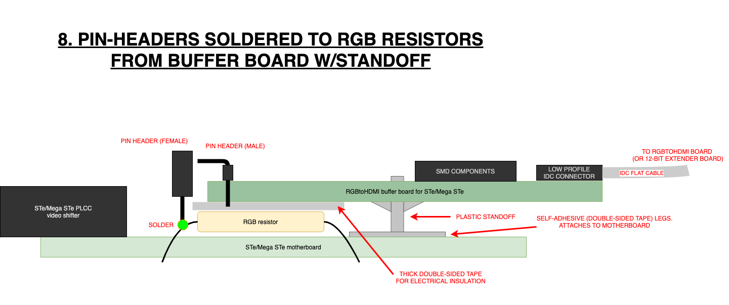
@DoG: I think the plastic standoffs with adhesive legs could work! :D

8. pin-headers soldered to RGB resistors from buffer board with standoff.png
8. pin-headers soldered to RGB resistors from buffer board with standoff.png (87.98 KiB) Viewed 27 times

The standoffs (two on the right side of the buffer PCB will probably suffice) would take care of a secure mounting plus raise the buffer PCB above the RGB/mono resistors and prevent any short circuiting from through-hole components from the buffer board (and some thick double-sided tape to the top of the RGB/mono resistors would add extra electrical insulation, cushioning and additional fastening).

This and the use of pin headers for connecting the board to the RGB/mono resistors would make for a clean, easy to replace/repair/remove modification :)

Obviously I'd have to make some measurements first as it's a tight fit in the STe, but with multiple heights of standoffs to choose from I think there's a good chance this will work out. In worst case, the IDC header connector will have to be mounted on the bottom side of the PCB. I'll have to look into what kind of options I have, but I think there are a few IDC connection options to choose from.
STe | MonSTer with dual IDE-CF memory card adapter | NEC Multisync 1990SXi | ST_ESSC | RSVE | Link '97 | Sony HD floppy drive/AJAX controller | Exxos HD floppy module | Battery-backed Ricoh realtime clock module | Discovery cartridge | C-Lab Unitor-2 | C-Lab Export | C-Lab Combiner | C-Lab Steady Eye | C-Lab Human Touch | Unicorn USB

💧Are you a good person? 💧Living Waters
Post Reply

Return to “HARDWARE DISCUSSIONS”