Page 98 of 110
Re: REV 3 - REV 5 - The beginning (ST536)
Posted: 23 Feb 2026 13:39
by exxos
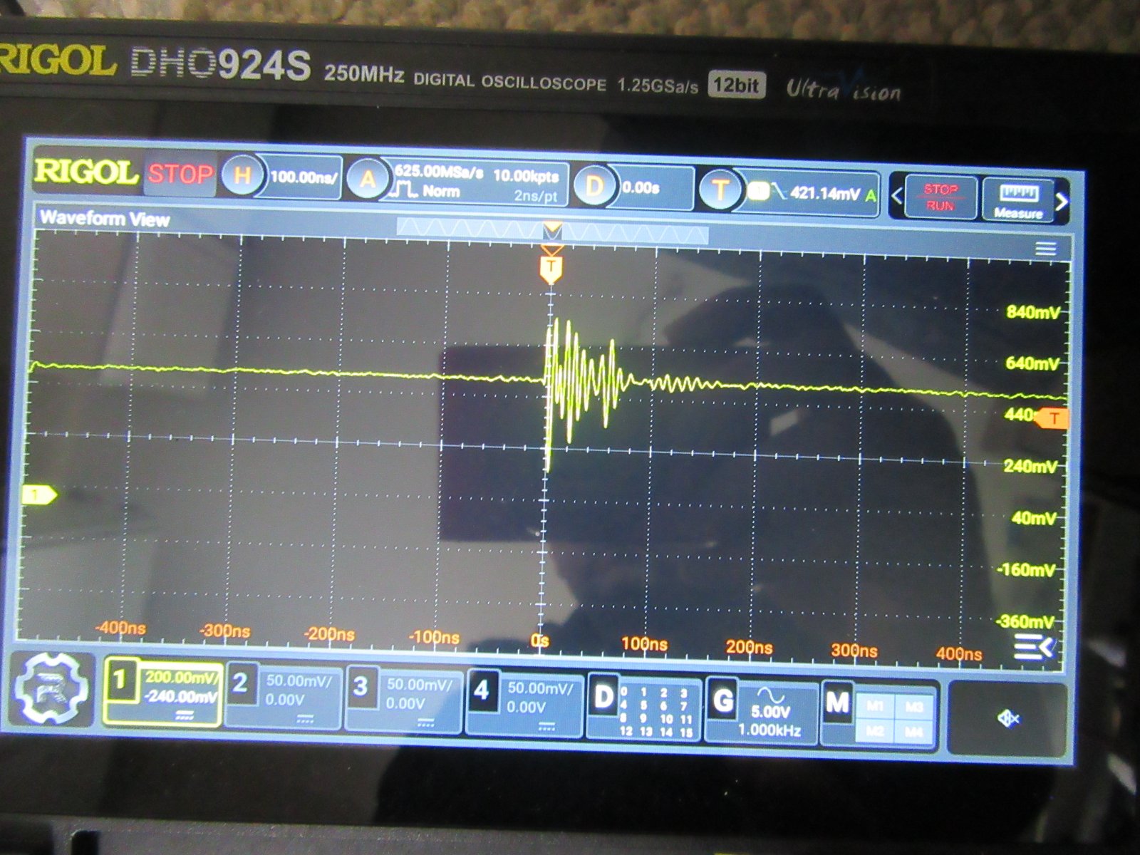
Another discovery which may or may not have been detectable with my old scope.. Certainly I might not have left it running long enough...
- IMG_4665.JPG (298.98 KiB) Viewed 1617 times

- IMG_4666.JPG (280.86 KiB) Viewed 1617 times
For the past couple of weeks I have had sporadic resets like someone is pressing the reset button. I suspected this happening before hence the test but I could not detect anything. But the new scope it has detected this type of chaos several times now.. But when it happens exactly seems rather sporadic. Properly generally around every half an hour...
I am probing on the H5 motherboard reset pin itself, and have given it all a good bash around various places on the board, and nothing seems to cause the reset signal to pulse like it does..
My only thought is that there is a bad connection on the pull-up resistor on the reset circuit somewhere :shrug:
Re: REV 3 - REV 5 - The beginning (ST536)
Posted: 23 Feb 2026 17:07
by exxos
Not yet being able to figure out the reset issue but I have just put a "reset debounce" in the code to avoid that problem (its not reset once all day since).
Upon reviewing the latest board rev 5.62.. I found a stupid issue...

- 0.PNG (118.25 KiB) Viewed 1596 times
Let me zoom in...(see how many people can spot it! ;) )

- 1.PNG (165.85 KiB) Viewed 1596 times
It's only saving grace here was I also flood filled the top layer for GND as well.. But still ... :roll:

- 2.PNG (144.46 KiB) Viewed 1596 times
Re: REV 3 - REV 5 - The beginning (ST536)
Posted: 24 Feb 2026 01:35
by exxos
2 boards did about 50 GB6 loops since adding the reset fix :thumbup:
2 other boards are totally dead. I need to continuity check the whole thing next :roll:
Re: REV 3 - REV 5 - The beginning (ST536)
Posted: 24 Feb 2026 12:37
by exxos
Was watching the scope like a hawk during various tests trying to see if ground bounce was in the mix. Indeed am seeing like 0.5v spikes which is a little worrying. Probably the 2 GND pins on a 68K socket isn't the best. The nothing much can be really improved because the H5 and ST536 has solid ground planes anyway.
What was a little surprising was that the noise was significantly less during STram, TTram cycles. It seemed to be worse during VDI enquire test but it was a really terrible anyway.
The other thing is it seems to have a "solid high" on the reset line then intermittently goes into noise pulses about ever 1-2uS then rings around 80mhz. But those 1uS pulses are not always there. When they are, the ringing isn't generally that bad anyway. But maybe there's some weird resonance going on between the H5 and ST536.
I'm going to add a few more caps on the 5V rail on the next gen boards to try and clamp the HF ringing better, though not much else can be done. Likely legislation would be better grounding between the 536 and motherboard, So I may add some exposed copper for soldering GND wires on like I did on the STE536 just in case..
The board which suddenly died or in the ultrasonic cleaner so I will continue to check them later to see if I can find anything amiss.. I've also been doing a lot of modifications to the next gen PCB as well. Mostly just need to tidy a few things up at the moment but probably will be more changes yet to do anyway.
Re: REV 3 - REV 5 - The beginning (ST536)
Posted: 24 Feb 2026 13:39
by exxos
Did not take long to find a problem with one of my R5.62 boards..

- Capture.PNG (202.39 KiB) Viewed 1544 times
The highlighted trace is A1. It traces from the 536 ROM, to the CPU, to the PLD, then nothing to A1 on the 68K header pins.. My money is on that via !
Scratch the way the solder resist and there is continuity between the header and at least that part of the via. Though I basically lose it underneath the PLD at that point :(
Time for some bodge wire...

- IMG_4678.JPG (297.01 KiB) Viewed 1544 times

- IMG_4679.JPG (217.25 KiB) Viewed 1544 times
:girldance: :girldance:
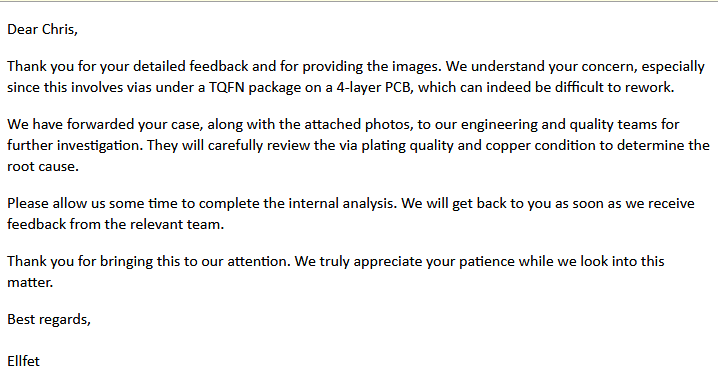
So JLC strikes again with bad vias :roll: I'm going to have to moan at them about all this! But probably be pointless anyway. :roll:
Re: REV 3 - REV 5 - The beginning (ST536)
Posted: 24 Feb 2026 20:20
by Darklord
Congratulations...but...that monitor... :lol:
Re: REV 3 - REV 5 - The beginning (ST536)
Posted: 24 Feb 2026 20:47
by Badwolf
Darklord wrote: 24 Feb 2026 20:20
but...that monitor... :lol:
I like it! It matches my eyes.
BW
Re: REV 3 - REV 5 - The beginning (ST536)
Posted: 24 Feb 2026 22:21
by exxos
Badwolf wrote: 24 Feb 2026 20:47
I like it! It matches my eyes.
Your eyes are pink and green ?? No wonder you not been around much :lol:
Re: REV 3 - REV 5 - The beginning (ST536)
Posted: 24 Feb 2026 22:22
by exxos
JLC email away....
- Capture.PNG (28.2 KiB) Viewed 1508 times
Re: REV 3 - REV 5 - The beginning (ST536)
Posted: 26 Feb 2026 10:50
by exxos
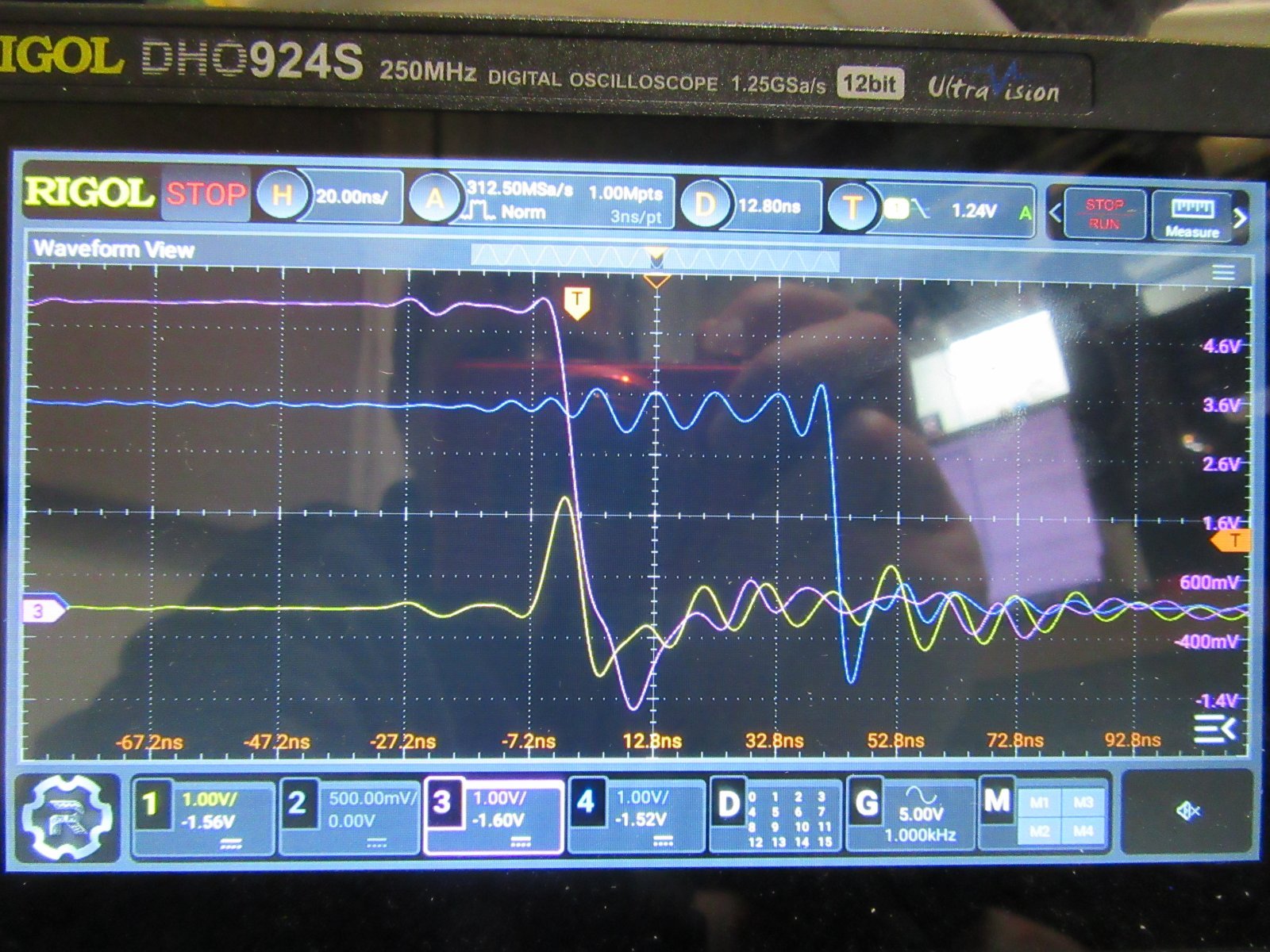
Made another discovery. Seems there is very bad ground bounce in particular when address or data line switch :roll:
PINK Data bus H5
YELLOW - GND
BLUE - BUS EN
- IMG_4694.JPG (362.29 KiB) Viewed 1462 times
Grounds were measured between the H5 PSU GND and ST536 GND. Incidentally the original TF536 actually has it worse. There is not much socket wise in the current stackup either.

- IMG_4706.JPG (192.29 KiB) Viewed 1462 times
It reminds me of problems I had right at the beginning on my 68000 boosters. Where under the PLCC 68K CPU was 2V ground bounce between CPU GND pins !
The redline just basically shows the ground current path between CPU pins.. That was literally all it took!

- ppcb1.jpg (138.04 KiB) Viewed 1462 times

- ppcb2.jpg (132.54 KiB) Viewed 1462 times
The DIP 68K pinout simply does not have enough grounds :roll:
The only workaround is to pass the whole data and address bus through something like 100R resistors to reduce the current through the GND. So I think there will be no more progress on this project for a few weeks because I have to design a patch board and wait for it to be manufactured and then repeat tests. :roll: