Page 5 of 6
Re: Falcon030 dead after Centuriontech CT60/CT60PSU incident - investigation begins
Posted: 05 Oct 2026 13:13
by exxos
Update from the owner. He's sent me a photo of the switch as it was after the incident, showing the soot.
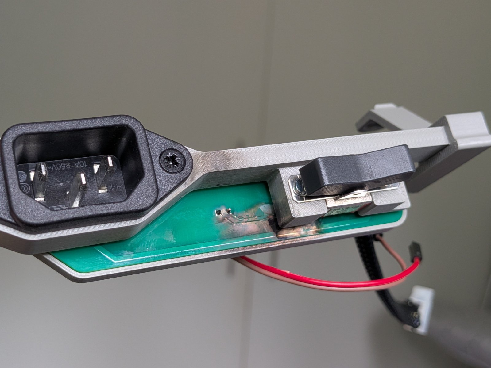
- PXL_20260818_161023326.jpg (188.97 KiB) Viewed 79 times
His order confirmation and documentation both state it is the 2025 version of the CT60PSU, and he only received it a few weeks before the incident.
He also contacted Pavel at the time and sent him this same photo. Towards the end of last week Pavel replied with just "Are you serious?". The owner has since confirmed to him that he is, and that everything in the timeline he emailed has actually happened. So he doesn't expect any repair, replacement or compensation to follow.
The owner's own view is that mixing mains and a logic signal in the same switch looks dangerous, and he'd much rather have had a normal power switch with a separate toggle for the 030/060 mode. That's the same concern a few of you have already raised.
The Falcon and PSU are on their way to me by Special Delivery and should arrive tomorrow. I'll update the thread once I've got it on the bench, though as mentioned I've not been well, so it may take a few days to get to it properly.
EDIT:
Hard to tell from the photo, but looking closer it seems the gap between the mains tracks on the PCB is not enough. My guess is it flashed over the two tracks first, causing the initial burn, then flashed over a second time to the CT60 pins. That would also fit the damage being on the board around the switch rather than inside the switch itself. I'll measure the clearances properly once it arrives, so treat this as a theory until then.
Re: Falcon030 dead after Centuriontech CT60/CT60PSU incident - investigation begins
Posted: 05 Oct 2026 13:29
by stephen_usher
That is very dangerous. You need anti-tracking slots in the PCB between the high voltage and low voltage sides. From what I remember there should be at least a 10mm gap between the traces as well. (The anti-tracking slots are there in case there has been a failure which causes the PCB to be heated and carbonised, allowing a current to flow through the substrate.)
Having them on the same switch is also incredibly bad as if you have a discharge then the space is small enough that the plasma will make all the atmosphere in the switch conductive for a short period.
It seems that Centurion Tech should not be allowed close to any mains or high voltage voltage devices.
Re: Falcon030 dead after Centuriontech CT60/CT60PSU incident - investigation begins
Posted: 05 Oct 2026 14:48
by rubber_jonnie
So looking at that picture, you can see that the two small pins which I would assume are the CT60 config pins and it's clear that the CT60 and Falcon have most likely suffered world ending damage as a result of a mains flashover to them.
There seems to be zero separation and this looks like an incident waiting to happen.
Whilst the double switch option is likely better I'd still argue that there is a danger of flashover from the mains switch to the mode selection switch, and they would be better off completely separated or have some sort of separator between them.
This mix of high and low voltages with little to no separation is a bit shocking (No pun intended) to me.
Re: Falcon030 dead after Centuriontech CT60/CT60PSU incident - investigation begins
Posted: 05 Oct 2026 14:49
by PhilC
It'll be interesting to see both sides of that PCB properly and the switch internals.
I think I'd have used a relay for the low voltage side to separate the voltages myself if it "had to be done from the one switch."
Re: Falcon030 dead after Centuriontech CT60/CT60PSU incident - investigation begins
Posted: 05 Oct 2026 18:05
by Maximilian
exxos wrote: 05 Oct 2026 13:13
PXL_20260818_161023326.jpg
Oh my...even worse than I imagined...
:dizzy:
PhilC wrote: 05 Oct 2026 14:49
I think I'd have used a relay for the low voltage side to separate the voltages myself if it "had to be done from the one switch."
If you are talking about the PSU with the 3 seperate modules on top... there are modules that have an "enable" pin that can be tied low(if I remember correctly), that would make a much cleaner sollution, relays have a tendency to fail over time..
(but everything is better than the original)
Re: Falcon030 dead after Centuriontech CT60/CT60PSU incident - investigation begins
Posted: 05 Oct 2026 18:56
by PhilC
@Maximilian I was talking about the use of a singular switch doing the high voltage and the low voltage switching being done through a relay, whether that be a mechanical coil type or a solid state relay, instead of the ridiculous situation of putting both high and low voltage circuits through the same small switch. The switch for the high voltage circuit should be single pole and of a suitable quality to offer proper protection to an expensive item. The low voltage side should be suitably isolated away from any high voltage sources. I would personally use two switches, located with the low voltage switching going directly to the CT60 as I've used on the ST536 which also uses the XL144.
I've used those all in one type power supply blocks many times (there's one on my desk as I type) and think I'd still rather keep their enable circuits away from a £2000+ difficult to replace computer system.
Remember optocouplers also fail and have a significantly smaller air gap between high and low voltage sides. Whereas most modern relays are rated for a million plus operations when correctly chosen for the application.
This is what I used to do as a very small part of my job as an engineer with more than 30 years experience.
Re: Falcon030 dead after Centuriontech CT60/CT60PSU incident - investigation begins
Posted: 05 Oct 2026 19:20
by PhilC
Anyway, this is an investigation thread, so let's see what @exxos finds when it arrives.
Re: Falcon030 dead after Centuriontech CT60/CT60PSU incident - investigation begins
Posted: 05 Oct 2026 19:26
by exxos
stephen_usher wrote: 05 Oct 2026 13:29
That is very dangerous. You need anti-tracking slots in the PCB between the high voltage and low voltage sides. From what I remember there should be at least a 10mm gap between the traces as well. (The anti-tracking slots are there in case there has been a failure which causes the PCB to be heated and carbonised, allowing a current to flow through the substrate.)
Having them on the same switch is also incredibly bad as if you have a discharge then the space is small enough that the plasma will make all the atmosphere in the switch conductive for a short period.
Jacob's ladder ;) also high voltage switches at the power stations have to have a huge fan to actually blow at the arc out otherwise when the contacts open current actually still flows :lol:
The regulations seem to be a bit all over the place in terms of a gap.. I got 6mm in my own head for a mains gap.. But really I was not even happy with that measurement..
Some regulations say basically 2.5mm is fine.. But it's the age-old problem of "on paper it works" and not "in reality". Mix in dirt, grime, temperature, humidity, and anything else you can think of... So yeah on the bench under ideal conditions, 2.5mm is fine.. In the real world, you're asking for massive amounts of failures.. Is clearly evident by what has happened already by multiple users..
I've seen power supplies using things like TO220 packages on the mains ,and the solder pads on the PCB end up close, where that gap is like 1 or 2mm... The amount of flashover's and burned PCBs I have seen in power supplies over the years because of silly things like that ! The "better" designs used those offset middle leg on packages.. physically separating the legs so such problems are less likely to happen !
So ironically, my initial hypothesis about the flashover on the switch itself was actually likely wrong, the problem is evidently a lot more dangerous and catastrophic than a simple switch failing. So basically we are at two major design flaws now.. And I have not even got the machine in front of me yet ! :lol:
It seems that Centurion Tech should not be allowed close to any mains or high voltage voltage devices.
:dualthumbup:
Re: Falcon030 dead after Centuriontech CT60/CT60PSU incident - investigation begins
Posted: 05 Oct 2026 19:36
by exxos
PhilC wrote: 05 Oct 2026 19:20
Anyway, this is an investigation thread, so let's see what @exxos finds when it arrives.
Should be here tomorrow, what time is anyone's guess.
I know my wording on the safety side may sound strong, but a PCB burning like that shouldn't be taken lightly. This isn't just about losing a Falcon. Boards can catch fire, and so can the case and anything else nearby. Plenty of people have their machines on a wooden desk or even sat on the lounge carpet, so I don't think I'm overstating it. I'd rather people took it seriously now than after it has happened to them.
The switch looks like a secondary issue at this point rather than the cause. I'll know more once I have it on the bench, but routing mains next to a 5V logic signal is asking for trouble whatever switch is fitted. Whether an up-rated switch was used or not is almost irrelevant. It's perfectly possible the switch itself is fine.
If the flashover is happening between tracks on the PCB, as it appears to from the photo, then unplugging the 5V mode select wire won't help, because the fault is on the board itself. Until I've measured the clearances and confirmed it, my advice to anyone with one of these would be to stop using it and take it out of the machine, rather than wait to see if the same thing happens to theirs.
Re: Falcon030 dead after Centuriontech CT60/CT60PSU incident - investigation begins
Posted: 05 Oct 2026 19:43
by alexh
Playing devil's advocate, you should also look for signs of possible user error. Could any of this be caused by a short caused by incorrect installation? Could it be caused by an attempt to refit the ESD shield?