Page 4 of 4
Re: TF536 doesn't _quite_ boot
Posted: 24 Oct 2020 00:03
by Aeberbach
It got put a way for a bit - it has all been FPGA learning here recently. Unfortunately Friday was a public holiday or else Mouser would have delivered a big box of parts, so I am waiting until Tuesday now but I expect I'll have the 536 going soon. I also had a hot air station and SMD tweezers arrive in the meantime. Finally I'm almost set up.
Re: TF536 doesn't _quite_ boot
Posted: 26 Oct 2020 07:08
by nikoskon
terriblefire wrote: 23 Oct 2020 07:53
The hard disk *should* work without the RAM chips installed but will not without the RAM CPLD programmed.
Yes, you are right about this, helps when you don't have solder bridges :oops:
Re: TF536 doesn't _quite_ boot
Posted: 07 Nov 2020 02:27
by Aeberbach
So, here's where it's at. I removed the RAM to turn it around and installed new RAM in the correct orientation. (Should have left it off, I know, to troubleshoot with less on the board.) The TF536 just sits there with some kind of VGA signal coming out of the A600 (monitor light is green) but no boot. With the TF536 removed DiagROM does boot as expected. Nothing feels warm. I can't see any solder bridges and everything is clean.
OK I thought, too much heat removing the RAM I might have cooked things nearby.
So I replaced the four 245 buffers that sit right under the RAM. I also removed a few of the passives on the back of the board and having measured them and found no problems, replaced them. No boot.
Even though the XC95288XL could be programmed by the Pi successfully I figured I may have cooked that too - possibly JTAG could function while I/O function was affected by heat. So I replaced that with a new one too. No problem programming it as before, xcs3prog in verbose mode taking 20 seconds, verifying, etc. No boot.
Next I pulled out the scope. Starting with the oscillator I expected to see a 100MHz waveform at 90% of 3.3V according to the data sheet:
https://au.mouser.com/datasheet/2/137/S ... 649548.pdf

- Scope trace oscillator output
- SDS00006.png (34.51 KiB) Viewed 4682 times
[/img]
Now that is close to 100MHz but the amplitude looks like about 600mV - what's going on there?
Here's the board. I've gone over this at high magnification and can see no problems.

- TF536
- IMG_3053.jpeg (274.48 KiB) Viewed 4682 times
Where should I look next?
Re: TF536 doesn't _quite_ boot
Posted: 07 Nov 2020 05:01
by Aeberbach
OK I am going to leave that last post there but there's no problem to be found.
The problem was that I swapped the 1k and 220R resistors on the riser. I can't even remember why I would ever have removed them now but they went on the wrong way and of course nothing boots when the board 68k is not correctly sleeping while the TF536 is correctly awake.
Now I have two TF536s that boot :D
Lemaru's riser is awesome. Once I get both into a working and tested state I'm going to solder the TF536 to it permanently so that the riser is as low as possible and the A600 can be closed.
Re: TF536 doesn't _quite_ boot
Posted: 07 Nov 2020 12:17
by Lemaru
It is often the simple things and that you don't spot for ages.
Glad you got it working. Any ideas on how to improve the adaptor then let us know.
Re: TF536 doesn't _quite_ boot
Posted: 12 May 2021 07:48
by Aeberbach
Finally I'm getting back to the TF536. I made a new riser from Lemaru's design on github, sanded down a new Augat PLCC socket, plugged in my 68030... and blow me down, DiagROM booted! 68030 success!
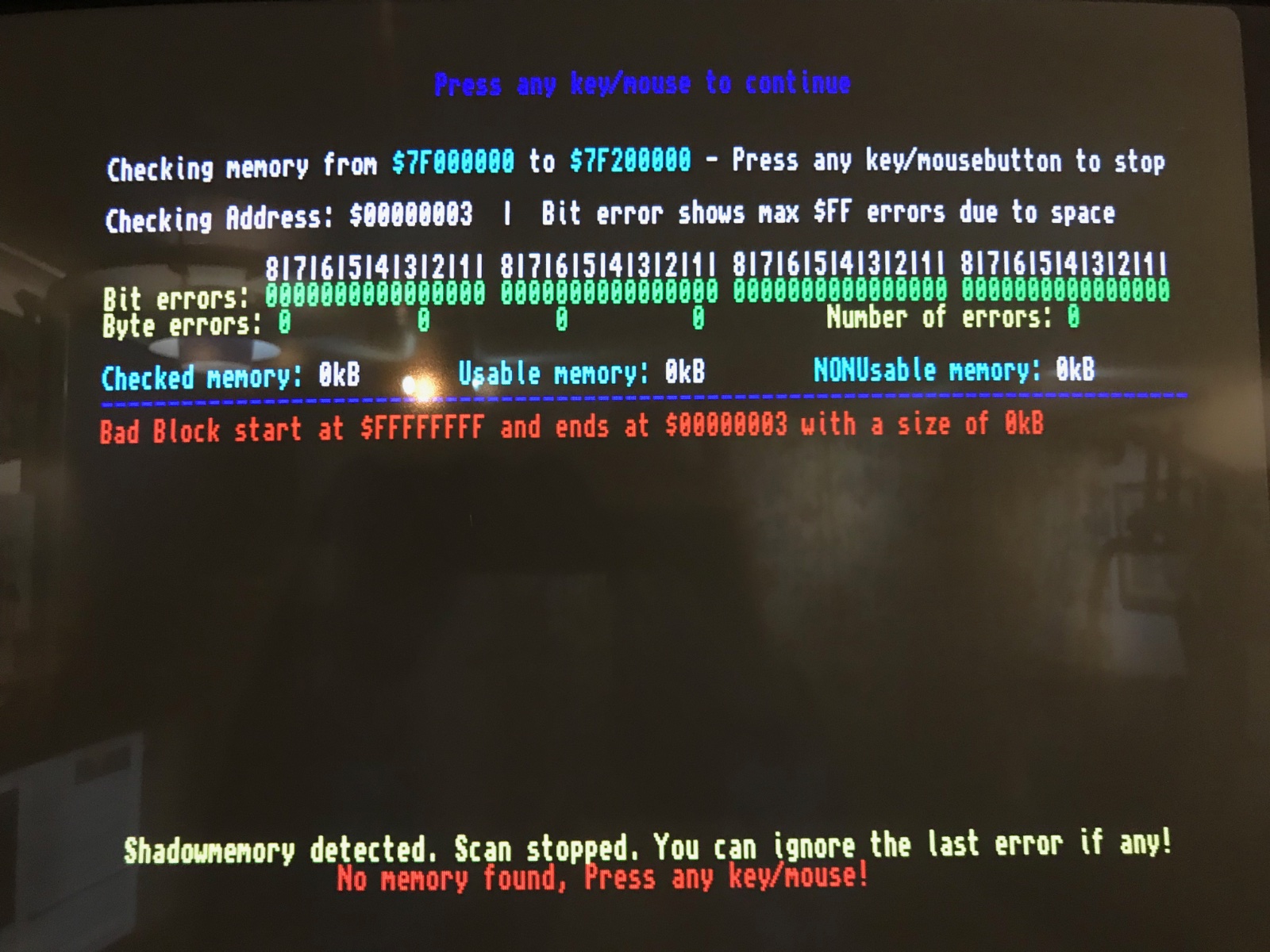
2M chip RAM scan is just fine. Fast RAM tests fail instantly, though I did buy and fit new RAM and after minute inspection I don't think there's any kind of problem with the soldering.
Any hints on what I should see from DiagROM or where to look if I get no RAM test progress at all?
I have inspected, reflowed, inspected again - no change. Reprogrammed CPLD with firmware from
viewtopic.php?f=93&t=3438 - no change.
Edit: Working, after replacing the four buffer chips below the RAM. I expect they got cooked when I removed the original RAM that I installed the wrong way around.

- IMG_0025.jpeg (391.77 KiB) Viewed 4041 times
- IMG_0026.jpeg (458.66 KiB) Viewed 4041 times

- IMG_0027.jpeg (355.97 KiB) Viewed 4041 times

- IMG_0024.jpeg (365.93 KiB) Viewed 4041 times
!Message from: Moderator
@Aeberbach, we have placed your attachments in-line so they display correctly in your post. Here's the
how-to guide.